Summary
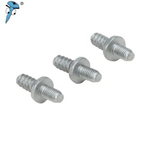
Self-tapping screws are high-strength fasteners with both self-tapping and fastening functions.
Different thread configurations have different effects on the fastening performance. By designing tightening and loosening tests, the installation torque selection, torque efficiency and loosening performance of two types of self-tapping screws were analysed in detail to provide a reference for the selection of metal self-tapping screws in engineering applications.
The comparison shows that:
The tapping torque of the “Type I” self-tapping nail is lower than that of the “Type II” nail, and the “Type I” self-tapping nail has a larger torque selection window and a higher safety factor for installation;
Type II tapping screws of the same size are more torque efficient than Type I tapping screws and consume less torque for the same increased clamping force;
It should be noted that due to the low tapping torque advantage of “Type I” tapping screws, “Type I” tapping screws require less torque for low clamping force installations and “Type II” tapping screws require less torque for high clamping force installations;
When used with aluminium alloy nuts, both types of tapping screws have good loosening resistance compared to metric screws, but the “Type II” tapping nail has better loosening resistance than the “Type I” tapping nail for the same size.
1
Background
With the rapid development of new energy vehicles, lightweight, safety, low cost, energy saving and environmental protection have become the trend in the modernization of automobiles.
In order to meet this trend, the aluminium alloying of automotive parts has made a breakthrough. The change from steel to aluminium, from casting to forging, from multiple parts to integrated design, these changes have brought great challenges to the technical development of fasteners, requiring more effort to design connection structures and optimise fastening solutions.
In recent years, metal self-tapping connections have shown excellent fastening properties in aluminium alloys, not only in terms of strength and the ability to connect a variety of structures, but also in terms of tapping and fastening functions.
The advantages of this connection structure are that a good fit reduces the risk of loosening and that it can be dismantled for repeated use.
With the development of application requirements and technology, various types of self-tapping screws have come to dominate the market. In practice, the size of the self-tapping nail, the type of thread, the type of head, the type of tail, the surface finish and the development of torque specifications all have a significant impact on the tightening performance of the entire joint structure.
The authors of this paper focus on two different thread configurations of metal self-tapping screws and analyse and compare the fastening properties produced by these two thread configurations to provide guidance on the selection of metal self-tapping screws for practical applications.
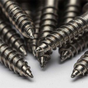
The first type of metal self-tapping nail is the “Type I”, which has the following advantages:
Low tapping torque;
High failure-to-tapping torque ratio;
Excellent axial positioning;
Stronger tapping-to-slip ratio;
Prevention of slipping of the internal thread;
Prevents loosening due to vibration;
Threads formed are compatible with metric fasteners.
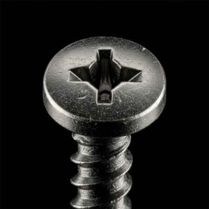
The second type of metal self-tapping nail is the “Type II”, which has the following advantages:
The conical thread forming band facilitates tapping and prevents slippage;
The 33° inclination angle reduces tapping torque;
High anti-loosening torque;
High connection strength due to the large threading area;
Higher pull-off torque;
The resulting threads are compatible with metric fasteners.
The authors have analysed and verified the fastening performance of two metal self-tapping nail thread configurations in the same test environment, which provides guidance for the selection and torque development of metal self-tapping screws in engineering applications.
2
Test content
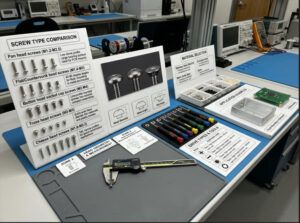
2.1 Test samples and equipment
The main samples and performance parameters used in the tests are shown in Table 1.
Table 1 Samples and performance parameters used for the performance tests of the two metal self-tapping screws
The main equipment used during the test is shown in Table 2.
Table 2 Equipment used in the performance tests of the two metal self-tapping screws
2.2 Test set-up
A schematic diagram of the equipment used during the test is shown in Figure 1(a);
The device during the test is shown in Figure 1(b);
A diagram of the apparatus during the vibration test is shown in Figure 1(c).
2.3 Test programme
2.3.1 Tightening to joint failure
As shown in Figure 1(a)(b), metric screws, “Type I” self-tapping screws and “Type II” self-tapping screws were fixed and the screws were tightened with torque testing equipment until the joint failed.
Test conditions: rotational speed 30 r/min.
2.3.2 Tightening to installation torque
As shown in Figure 1(a)(b), fix the metric screws, “Type I” self-tapping screws and “Type II” self-tapping screws respectively, tighten the screws to the installation torque using the torque test equipment and record the torque, angle of rotation and tensile force of the screws using the data acquisition equipment.
Test conditions: rotational speed 30 r/min, installation torque selected from section 1.3.1 statistics.
2.3.3 Static decay test
As shown in Fig. 1(a)(b), fix metric screws, “Type I” self-tapping screws and “Type II” self-tapping screws respectively, tighten the screws to the installation torque with the torque test equipment, record the maximum clamping force, and after 30 min, record the remaining clamping force.
Test conditions: speed 30r/min.
2.3.4 Vibration decay test
As shown in Figure 1(c), fix metric screws, “Type I” self-tapping screws and “Type II” self-tapping screws respectively, tighten the screws to the same clamping force with the tightening device, record the clamping force and the number of vibration cycles during vibration.
Test conditions: amplitude 0.8 mm, vibration load 1 kN, number of cycles 500.
This experiment uses the force after a 50% reduction in clamping force as the shear breaking force.
3
Results and discussion
3.1 Analysis of mounting torque selection
Figure 2(a) shows the comparison of the tapping torque and yielding torque of two metal self-tapping screws of different specifications.
It can be seen that there is little difference in the tapping torque for the same threaded structure of different specifications. 4.957 and 5.266 N-m for “Type II” M5 and M6 respectively;
Comparing the tapping performance of these two thread configurations, the tapping torque of the “Type I” self-tapping nail is significantly lower than that of the “Type II”, with a reduction of around 1.3 N-m.
The study shows that the advantage of the “Type I” tapping performance is mainly due to the triangular leaf-shaped thread structure, which has a triangular cross-section to reduce the tapping torque and thus meet the need for lower tapping torque,
This thread structure also provides better axial positioning and reduces installation torque consumption in other areas.
In terms of yield torque values for both thread configurations, there is little difference between the two types of tapping screws in the M5 size with a yield torque of 13.111 and 13.186 N-m respectively, while the “Type I” tapping nail in the M6 size has a yield torque of 17.87 N-m and the “Type II” tapping nail has a yield torque of 13.111 and 13.186 N-m respectively. The yield torque of the “Type I” self-tapping screws is 17.87 N-m and the yield torque of the “Type II” self-tapping screws is 21.039 N-m.
From the hardness test results, the hardness of the “Type I” self-tapping screws was significantly lower than that of the “Type II” self-tapping screws, resulting in a smaller clamping force required for “Type I” yielding than “Type II”, so the yielding torque of the “Type I” self-tapping screws was less than that of the “Type II” self-tapping screws.
Fig. 2(b) shows a comparison of the tapping torque/yield torque ratio for two different sizes of metal self-tapping screws.
For M5 size screws, the tapping/yielding torque ratio is 0.277 for “Type I” self-tapping screws and 0.378 for “Type II” self-tapping screws.
For M6 size screws, the tapping/yielding torque ratio is 0.202 for “Type I” and 0.250 for “Type II” screws.
This advantage in tapping performance is due to the novelty of the thread construction.
Figure 2 Torque test results for two different sizes of metal self-tapping screws
The thread structure of the “Type I” is characterised by:
Triangular leaf-shaped thread structure;
Radius threads;
The tapping creates its own and hardened mating thread, as shown in Fig. 2(c).
The result of this is that the torque range of the “Type I” self-tapping nail is significantly greater than that of the “Type II” self-tapping nail, ensuring safe torque selection and increasing the safety factor of the installation, avoiding the risk of failure due to small variations in torque.
In summary: the tapping torque of a “Type I” self-tapping nail of the same size is lower than that of a “Type II” self-tapping nail; the tapping/yielding torque ratio of a “Type I” self-tapping nail is lower, The torque selection range is greater and the safety factor of the installation is greater.

3.2 Torque efficiency analysis
Figure 3(a) shows a comparison of the torque/clamping force ratios of two different sizes of metal self-tapping screws.
It can be seen that:
For M5 size screws, the ratio of torque and clamping force for “Type I” self-tapping screws is 0.818N-m/kN, i.e. the torque required to increase the clamping force by 1 kN is 0.818N-m, while the ratio of torque and clamping force for “Type II” self-tapping screws is 0.549N-m. 0.549 N-m/kN;
For M6 screws, the ratio of torque to clamping force is 1.02 N-m/kN for “Type I” self-tapping screws and 0.816 N-m/kN for “Type II” self-tapping screws, i.e. for every additional 1 kN, “Type I” tapping screws consume 0.204 N-m more torque than “Type II” tapping screws.
A comparison of the torque required to install three screws of different sizes to the same clamping force can be seen in Figure (b):
For M5 size screws, the torque required to install to a clamping force of 5kN is 7.698, 7.704 and 7.559N-m for “Type I”, “Type II” and metric screws respectively, with slight differences between the three, but the differences are not significant. There are slight differences between the three, but they are not significant, with metric screws being relatively low.
For M6 screws, the torque required to install a clamping force of 7 kN is 11.047, 10.828 and 9.422 N-m for “Type I”, “Type II” tapping screws and metric screws respectively, The torque required for “Type I” self-tapping screws is significantly higher than that required for “Type II” and metric screws, a phenomenon that is a direct indication of the torque efficiency of the threaded construction.
The lower torque of metric screws is understandable because the mounting torque is not required for tapping to form internal threads, so the torque required to produce the same clamping force is lower.
The reason why the torque required to produce the same clamping force is higher for “Type I” than for “Type II” is that the frictional contact area of the threaded part of the “Type I” self-tapping nail is greater than that of the “Type II” self-tapping nail, the greater the frictional contact area, the more torque is consumed, and the torque used to produce the clamping force at this time is considerably lower.
In a joint system, the torque consumption consists of 3 main parts:
A part of the torque is used to generate the clamping force,
One part of the torque is consumed by the contact friction of the threads and the remaining part by the contact friction of the squeezing surface,
The ratio of torque consumption for the three components is approximately 1:4:5,
As shown in equation (1).
The “Type II” self-tapping nail has a 33° thread configuration, which allows the connection system to have a smaller thread friction area and therefore requires less torque per unit increase in clamping force, as shown in Figure 3(c).
From the torque and clamping force curves for M5 and M6 metal tapping screws in Fig. 3(c) and (d), it can be seen that the “I-type” tapping screws are more advantageous in installation systems with lower clamping force requirements.
For M5 tapping screws with a clamping force below 4.87 kN, the “Type I” is more advantageous than the “Type II”, and for clamping forces above 4.87 kN, the “Type II” is more advantageous than the “Type I”. If the clamping force is higher than 4.87kN, the “Type II” consumes less torque than the “Type I”; for M6 tapping screws with a clamping force below 5.37kN, the “Type I” consumes less torque than the “Type II”. The “Type I” consumes less torque than the “Type II” for self-tapping screws with clamping forces below 5.37 kN, and conversely, the “Type II” has the advantage over the “Type I”.
The reason for the predominance of the “Type I” over the “Type II” at low clamping force requirements is that the “Type I” has a low tapping torque and, with a small clamping force requirement, more torque is available to The reason for this is that the “Type I” has a low tapping torque.
The reason why the “Type II” requires a lower clamping force than the “Type I” is that the “Type II” has a higher torque efficiency, resulting in an increase of the same clamping force. The reason for this is that the “Type II” has a higher torque efficiency, resulting in a lower torque value for the same increased clamping force.
In summary, the torque efficiency of “Type II” self-tapping screws of the same size is higher than that of “Type I” self-tapping screws; in the case of low clamping force requirements, “Type I” takes up more than “Type II”. At low clamping forces, the “Type I” has an advantage over the “Type II”, as the “Type I” consumes less torque when mounted to the same clamping force; at high clamping forces, the “Type II” has an advantage over the “Type I”. The “Type II” is more advantageous than the “Type I” for high clamping force requirements.
3.3 Anti-loosening performance analysis
3.3.1 Static decay rate analysis
Figure 4 shows a comparison of the decay rate of the clamping force of three types of screws of different sizes installed to the same torque and left to stand for 30min.
When the mounting torque is 9N-m, the clamping force of M5 “Type I”, “Type II” and metric screws is 5.943, 5.833 and 6.249kN respectively. The static decay rate of the clamping force for the three screws was 12.91%, 12.88% and 7.97% respectively.
When installed to the required torque, the clamping forces for M6 “Type I”, “Type II” and metric screws were 8.104, 11.215 and 12.482 kN respectively. The static decay rates of the clamping forces of the three screws were 9.46%, 8.85% and 5.20% respectively.
Comparing the decay rates of the three screws, it can be seen that the decay of the two metal self-tapping screws is significantly greater than that of the metric screws.
This is due to the fact that the formation of the self-tapping threads results in a high number of stress concentrations, and the slow stress release process during the resting process results in a certain degree of reduction in clamping force, with stress concentrations mainly found at the root and tip of the thread.
The reasons for the greater static decay in the “Type I” than in the “Type II” are:
(1) From the strength and hardness of the two types of self-tapping screws themselves, the hardness of “Type I” is lower than the strength of “Type II”, low hardness and toughness, which will produce a certain degree of creep relaxation, so the static decay of the clamping force is more.
(2) “Type II” self-tapping nail 33 ° screw structure has a better self-locking anti-loosening performance, to a certain extent, to reduce the static decay of the clamping force.
As shown in Figure 2(c), the structural advantages of the “Type II” are:
33° thread configuration;
Metric matching thread structure;
Round cross section.
Fig. 4 Comparison of the attenuation rates of the clamping forces of three different screw sizes mounted to the same torque and left to stand for 3 0 min.
3.3.2 Vibration decay rate analysis
Figure 5 shows a comparison of the residual clamping force after 500 transverse vibrations for three screws of size M6 mounted to a clamping force of 4 kN.
The residual clamping force after the vibration test for the three types of screws “Type I” self-tapping screws, “Type II” self-tapping screws and metric screws were 2.137, 2.933 and 2.00 kN respectively, and the decay values of the clamping force were 1.863, 1.067 and 1.997 kN respectively. 1.997kN.
It is interesting to note that the metric screw is able to reduce the clamping force to the set target clamping force (50% of the initial clamping force) after 100 vibration cycles.
Comparing the decay of the clamping force of the “Type I” and “Type II” metal tapping screws with that of the metric screws, it can be seen that the loosening resistance of the two metal tapping screws is significantly better than that of the metric screws, due to the fact that both metal tapping screws have certain loosening considerations in the design part of the thread structure:
(1) The “I-shaped” triangular leaf-shaped thread structure provides a certain self-locking effect when tapped against the nut.
(2) The “Type I” radius thread structure provides a large frictional contact area between the threads and improves the loosening performance.
(3) The 33° thread structure of the “Type II” self-tapping nail increases the effective engagement area between the threads, thus allowing the internal thread material to absorb more vibration energy and achieving a good anti-loosening effect.
Comparing the “Type I” and “Type II” metal tapping screws, it can be seen that the “Type II” tapping nail has better loosening resistance than the “Type I “Under the same vibration conditions, the residual clamping force of “Type II” self-tapping screws is significantly higher than that of “Type I”.
From the comparison of the data: although the radius thread structure of the “Type I” can increase the thread engagement area to a certain extent, the effective engagement area of the “Type II” is still better than that of the “Type I”. “In terms of frictional contact], the “Type II” is less prone to slackening.
In addition, the decay of the clamping force is related to the creep and stress relaxation of the screw. From the hardness test results, the material strength of “Type I” is lower than that of “Type II”, so under the same test conditions, “Type I” self-tapping screws undergo a greater degree of creep and stress relaxation than “Type II”, which the authors believe is one of the reasons for the difference in the decay of the clamping force of the two types of self-tapping screws.
Figure 5 Comparison of the residual clamping force after 500 transverse vibrations for three screws with an initial clamping force of 4 kN
In summary, the same size of self-tapping nail has a very good anti-loosening performance compared with metric screws;
After the same number of transverse vibrations, the residual preload force of the “Type II” tapping screws is greater than that of the “Type I” tapping screws and the “Type II” tapping screws have better loosening resistance.
Finally
In this paper, the authors analyse and compare the fastening performance of metal self-tapping screws with two different thread configurations by designing different test schemes and obtain the following conclusions:
(1), the same specification of “Type I” self-tapping nail tapping torque than the “Type II” self-tapping nail lower, from the tapping / yield torque ratio comparison can be seen, “Type I” self-tapping nail installation The comparison of the tapping/yielding torque ratios shows that the “Type I” tapping screws have a greater range of torque options and a greater safety factor for installation. This advantage is mainly due to the triangular shape of the threaded end face of the “I” tapping nail, which reduces the tapping torque to a large extent.

(2) The torque efficiency of “Type II” tapping screws of the same size is higher than that of “Type I” tapping screws, i.e. the torque required to increase the clamping force per unit is higher for “Type II” tapping screws than for “Type I” tapping screws. Type II” tapping screws require less torque per unit of clamping force than “Type I” tapping screws. This advantage is mainly due to the 33° thread inclination of the “Type II” self-tapping nail, which effectively reduces the frictional consumption of the threaded part and thus increases the utilisation of torque.
(3) When used with nuts made of aluminium alloy, both “Type I” and “Type II” self-tapping screws have excellent anti-loosening properties compared to metric screws; the same specification of “Type II “Type II” self-tapping screws have better loosening properties than “Type I” self-tapping screws. The loosening advantages of the tapping screws are mainly due to their respective loosening-proof thread design. The “Type II” self-tapping nail has a 33° thread structure and a large effective thread engagement area.