In a handheld medical device, a single M2 pan-head screw sits 1.4 mm from a signal trace carrying microvolt-level analog readings. If that screw is ferromagnetic, it distorts the local field and injects noise into the measurement. If it is conductive but ungrounded, it becomes an antenna. If it is too long by 0.5 mm, it bottoms out in the boss and cracks the plastic housing on the 3,000th unit off the line. If it is the correct screw but torqued 0.1 N·m above specification, the brass insert pulls out of the housing and the entire assembly goes to rework.
These are not hypothetical scenarios. They are defect reports from production lines that treated screw selection as an afterthought — something to fill in on the bill of materials after the “real” engineering was done. In precision electronics, every fastener decision interacts with electrical, thermal, mechanical, and chemical variables simultaneously. Getting one variable wrong costs time, money, and reputation.
This guide walks through every decision that matters when choosing small head screws for electronics: application analysis, material selection, head style, thread type, dimensional fit, surface finish, driver compatibility, standards compliance, sourcing, installation, and verification. The information here draws on production data, industry standards, and the manufacturing expertise of Prince Fastener, which produces machine screws in stainless steel, brass, and carbon steel across sizes from M1.6 to M12 — covering the full range of precision electronics applications.
Understand Your Application
Define Load, Environment, and Space Constraints
Before opening a fastener catalog, answer three questions about the joint. First, what loads will the screw see? In electronics, primary loads are rarely structural in the traditional sense — the screw is not holding up a bridge. Instead, the loads are clamp load (keeping a gasket compressed or maintaining contact between a heat sink and a component), vibration load (preventing loosening during transport or operation near motors, fans, or vehicles), and impact load (surviving drop tests per IEC 60068-2-31 or MIL-STD-810). Quantify these in Newtons and frequency ranges before selecting a size.
Second, what is the operating environment? A screw inside a sealed laboratory instrument in a climate-controlled room faces a very different corrosion and thermal challenge than a screw on the exterior panel of a marine radar unit. Environmental variables include temperature range (affects material expansion, lubricant viscosity, and creep behavior in plastic bosses), humidity and chemical exposure (determines corrosion risk and finish requirements), and ingress protection rating (IP-rated enclosures may require captive screws, O-ring-compatible heads, or specific torque values to maintain seal compression).
Third, what are the space constraints? In electronics, clearance is measured in tenths of millimeters. Head height, head diameter, and total screw length must fit within the mechanical envelope without interfering with adjacent components, cable routing, or removable covers. A socket cap head screw (DIN 912) has a head height roughly equal to its diameter — approximately 3 mm for an M3 — while a pan head (DIN 7985) is only about 2.4 mm tall for the same M3. That 0.6 mm difference can determine whether a shielding can fits over the assembly.
Identify Electrical and Thermal Considerations
In precision electronics, screws are not electrically neutral. A metallic screw creates a conductive path between the components it connects. This can be intentional — chassis screws often serve as grounding points, establishing the equipotential bond between a PCB ground plane and a metal enclosure. Or it can be harmful — a screw bridging two conductive surfaces at different potentials creates a short circuit or a ground loop.
Thermal behavior matters in two scenarios. In heat-sink mounting, the screw must transfer clamping force without acting as a thermal bottleneck. Stainless steel’s thermal conductivity (~15 W/m·K) is dramatically lower than aluminum’s (~205 W/m·K) or copper’s (~400 W/m·K), so a stainless screw in a heat-sink application should be positioned and sized to maximize pad-to-pad contact rather than relying on the screw itself for heat transfer. In high-temperature applications (power electronics, automotive ECUs), the screw material must maintain its mechanical properties at operating temperature — carbon steel begins to lose strength above 300°C, while Inconel and titanium alloys remain stable to 500°C+.
Material and Alloy Options
Material Properties Overview (Strength, Corrosion Resistance, Temperature Tolerance)
Material selection for electronics screws involves balancing six properties: tensile strength (determines clamp load capacity), yield strength (determines the safety margin before permanent deformation), corrosion resistance (determines service life without protective coatings), density (affects weight in portable or aerospace applications), magnetic permeability (determines compatibility with sensitive circuits and MRI environments), and electrical conductivity (determines grounding capability and short-circuit risk).
| Property | 304 Stainless Steel (A2-70) | 316 Stainless Steel (A4-70) | Titanium Grade 5 (Ti-6Al-4V) | Aluminum 7075-T6 | Brass (CDA 360) |
|---|---|---|---|---|---|
| Tensile Strength (MPa) | 700 | 700 | 950 | 572 | 385 |
| Yield Strength (MPa) | 450 | 450 | 880 | 503 | 310 |
| Density (g/cm³) | 7.93 | 7.98 | 4.43 | 2.81 | 8.50 |
| Corrosion Resistance | Good | Excellent | Excellent | Moderate* | Good |
| Magnetic Permeability | ~1.02 (non-magnetic) | ~1.01 (non-magnetic) | ~1.00 (non-magnetic) | ~1.00 (non-magnetic) | ~1.00 (non-magnetic) |
| Electrical Conductivity (% IACS) | 2.5% | 2.3% | 3.1% | 33% | 26% |
| Max Service Temp (°C) | 870 | 870 | 400 | 150 | 200 |
| Relative Cost (M3×8) | 1× (baseline) | 1.3× | 8–12× | 2–3× | 1.5× |
*Aluminum requires anodizing or other surface treatment for corrosion resistance in humid environments. Data compiled from ASM International material datasheets. Cost ratios are approximate and vary by order volume and supplier.
Common Alloys Used in Electronics (Stainless Steel, Titanium, Aluminum)
Austenitic stainless steel (304/A2 and 316/A4) accounts for the majority of screws used in electronics enclosures, PCB mounting, and general instrument assembly. Grade 304 (18% chromium, 8% nickel) provides adequate corrosion resistance for indoor applications and is non-magnetic in the annealed condition — critical for avoiding interference near sensitive analog circuits, Hall-effect sensors, and inductors. Grade 316 adds 2–3% molybdenum for significantly better resistance to chloride corrosion, making it the standard for marine electronics, outdoor communications equipment, and any device that may be exposed to salt spray or industrial chemicals. Prince Fastener’s comparison of 304 vs. 316 stainless steel provides detailed data on when the cost premium of 316 is justified by the environmental demands of the application.
Titanium Grade 5 (Ti-6Al-4V) offers the highest strength-to-weight ratio of any common fastener material — approximately 35% stronger than 304 stainless at 44% less weight. It is virtually non-magnetic, highly corrosion-resistant, and biocompatible. In electronics, titanium screws appear in aerospace avionics (where every gram matters), implantable medical devices (where biocompatibility is mandated), and high-end portable instruments (where weight and corrosion performance justify the 8–12× cost premium over stainless).
Aluminum alloys (6061-T6, 7075-T6) are used when weight is the dominant constraint and loads are low. An M3 aluminum screw weighs roughly one-third what the same screw in stainless steel weighs. The trade-off is lower tensile strength and poor galvanic compatibility with dissimilar metals — an aluminum screw in a steel enclosure will corrode rapidly unless isolated with a washer or insulating bushing. Aluminum screws are common in consumer electronics housings, drone frames, and portable test equipment.
Brass (CDA 360, CDA 270) is selected primarily for its electrical conductivity and machinability. In electronics, brass screws serve as grounding contacts, terminal fasteners, and decorative hardware on audio equipment and professional instruments. Prince Fastener’s brass screw line covers machine screws in pan head, flat head, and socket head configurations across M2 to M6, which spans the typical range for electronics grounding and terminal applications.
Electrical Conductivity Considerations and Non-Conductive Requirements
Some applications require complete electrical isolation between the screw and the surrounding components. In RF circuits, a metallic screw inside a tuned cavity can detune the resonance and degrade performance. In high-voltage power supplies, a conductive screw bridging a creepage gap can cause arcing or breakdown. In these cases, non-conductive alternatives include nylon screws (suitable for low-load, low-temperature applications), PEEK (polyether ether ketone) screws (rated to 250°C continuous, with tensile strength around 100 MPa — adequate for PCB mounting but not structural joints), and ceramic screws (used in extreme-temperature or ultra-high-frequency applications).
When a metallic screw must be used in an insulating application — for example, where nylon’s strength is inadequate — the screw can be isolated with nylon shoulder washers and insulating bushings that prevent contact between the screw shank and the conductive housing.

Head Styles for Precision Electronics
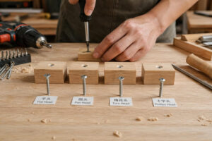
Pan Head, Button Head, and Socket Cap Head — When to Use
Head style selection in electronics involves three competing requirements: profile height (lower is better for space-constrained designs), bearing surface area (larger heads distribute clamp load over a wider area, reducing stress on plastic housings), and tool access (different head heights and drive recesses require different driver lengths and angles).
Pan head (DIN 7985 / ISO 7045) is the default choice for general electronics assembly. Its low profile (head height ≈ 60% of head diameter) and wide bearing surface make it suitable for clamping plastic, sheet metal, and PCB material without concentrating stress. A pan head M3 screw has a head diameter of approximately 6.0 mm and a head height of approximately 2.4 mm — compact enough for most enclosures while providing a stable, flat bearing surface. Prince Fastener’s pan head machine screws are available in 304 and 410 stainless steel across standard metric sizes.
Button head (ISO 7380) is a socket-drive screw with a low, domed profile — head height approximately 50% of head diameter for a given size. Its aesthetically clean appearance makes it popular on the exterior panels of professional instruments, audio equipment, and medical devices where screws are visible to the end user. The hex socket drive provides higher torque capacity than a Phillips recess of the same size, which is useful when screwing into metal inserts or when vibration locking is required.
Socket cap head (DIN 912 / ISO 4762) has the tallest profile of the three — head height approximately equal to head diameter — but also the highest torque capacity and the deepest hex socket for secure driver engagement. In electronics, socket cap heads appear in structural applications (mounting heavy transformers, motor brackets, or heatsink assemblies) and in locations where the head is recessed into a counterbore, negating the height penalty. Prince Fastener manufactures socket cap screws in carbon steel, stainless steel (304/316), and alloy steel with various plating options.
Socket Types and Compatibility with Drivers (Phillips, Torx, Hex)
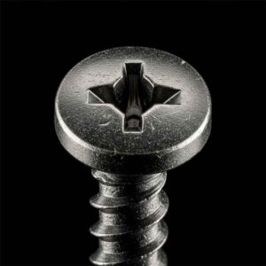
In electronics production, driver compatibility affects cycle time, defect rate, and operator fatigue. Phillips (Type H / ISO 8764) is the most common cross-recess drive for small machine screws, but it cams out under moderate torque — a characteristic that becomes a production defect when cam-out strips the recess on a screw that is recessed inside a housing and now cannot be removed for rework.
Torx (ISO 10664) provides significantly better cam-out resistance than Phillips at the same size. In the M2–M3 range, Torx T6 through T10 are the relevant sizes. The six-lobe geometry distributes torque uniformly and allows lower insertion force, which is valuable when assembling plastic housings where overtorque cracks bosses.
Hex socket (ISO 4762) is the standard for socket cap head and button head screws. In the M2–M3 range, hex keys of 1.5 mm and 2.5 mm are used. The hex recess provides excellent torque transfer but requires axial alignment — the key must be inserted straight, which can be awkward in tight assemblies. L-keys with ball ends address this by allowing up to 25° of angular misalignment.
Thread Types and Pitch Considerations
Coarse vs. Fine Thread Choices for Electronics Assemblies
Every metric screw size has a standard (coarse) pitch and one or more fine-pitch options. For M3, the coarse pitch is 0.5 mm (one full thread per 0.5 mm of length) and the fine pitch is 0.35 mm. The choice between them affects assembly speed, vibration resistance, adjustment precision, and plating compatibility.
Coarse threads are the default for most electronics assemblies. They are faster to install (fewer turns per mm of engagement), more tolerant of plating buildup (the wider thread valleys accommodate the 5–15 µm of zinc or nickel that coated screws carry), less prone to cross-threading during manual assembly, and stronger in shear (the larger minor diameter of coarse threads provides a larger cross-sectional area at the thread root).
Fine threads are preferred in three specific scenarios: when precise adjustment is needed (fine pitch provides smaller incremental advance per revolution, which is useful for adjusting contact pressure on springs, micrometers, or optical mounts), when vibration resistance must be maximized without a threadlocker (the shallower helix angle of fine threads makes them inherently more resistant to vibration-induced loosening), and when threading into thin-walled material where the additional thread engagement of a finer pitch provides better pull-out resistance.
| Size | Coarse Pitch (mm) | Fine Pitch (mm) | Minor Dia. – Coarse (mm) | Minor Dia. – Fine (mm) | Common Electronics Use |
|---|---|---|---|---|---|
| M1.6 | 0.35 | 0.20 | 1.17 | 1.35 | Micro connectors, watches, micro-optics |
| M2 | 0.40 | 0.25 | 1.51 | 1.69 | Smartphones, tablets, small PCB mounts |
| M2.5 | 0.45 | 0.35 | 1.95 | 2.07 | PCB standoffs, laptop drives, small enclosures |
| M3 | 0.50 | 0.35 | 2.39 | 2.57 | General enclosure, PCB mounting, heat sinks |
| M4 | 0.70 | 0.50 | 3.14 | 3.39 | Heavier enclosures, rack equipment, power supplies |
| M5 | 0.80 | 0.50 | 4.02 | 4.39 | Rack-mount equipment, large instrument panels |
Metric vs. Imperial Threading and Compatibility with Components
Electronics manufactured in or for Asian and European markets almost universally use metric threads. North American electronics design increasingly uses metric as well, driven by the global supply chain for components, connectors, and enclosures that are dimensioned in millimeters. However, legacy designs and certain standards (notably 19-inch rack mounting per EIA-310, which uses #10-32 UNF and #12-24 UNC screws) maintain imperial threading.
Mixing metric and imperial screws in the same assembly is a persistent source of field failures. An M3 screw (3.0 mm major diameter, 0.5 mm pitch) is superficially similar to a #4-40 UNC screw (2.845 mm major diameter, 0.635 mm pitch) — the diameters are close enough that the wrong screw can be started in the wrong hole, but it will cross-thread and strip within a few turns. Preventing this requires clear drawing annotations (specifying thread designation on every fastener callout), segregated bin storage on the assembly line, and — for critical assemblies — go/no-go thread gauges at incoming inspection.
Size, Length, and Diameter Decisions
Selecting Diameter and Length for Adequate Thread Engagement
The rule of thumb for minimum thread engagement in steel-to-steel joints is 1× the nominal screw diameter (e.g., 3 mm of engaged thread for an M3 screw). In steel-to-aluminum, increase to 1.5×. In steel-to-plastic, increase to 2–2.5×. These minimums ensure that the threads carry the design load without stripping the internal thread, even under repeated assembly and disassembly cycles.
Screw length must account for the total stack-up: head bearing surface, any washers, the clamped material thickness, any standoff or spacer, and the engaged thread length. In practice, engineers add 1–2 mm to the calculated minimum to provide manufacturing tolerance margin. Too long is as bad as too short — a screw that bottoms out in a blind hole applies zero clamp load to the joint (all the torque goes into compressing the screw against the hole bottom rather than pulling the clamped materials together).
Clearance, Stand-Off, and Fit with PCB Holes or Standoffs
PCB mounting holes are typically 0.2–0.3 mm larger than the screw’s nominal diameter to allow for board-level positional tolerance and to prevent the screw from touching the annular ring or trace copper. For M3 screws, a 3.2 mm or 3.3 mm mounting hole is standard per IPC-2221 guidelines. For M2.5, a 2.7 mm hole is typical.
Standoff height (the gap between the PCB underside and the mounting surface) must clear the tallest through-hole component lead or solder joint on the bottom of the board. Standard standoff heights of 5 mm, 6 mm, 8 mm, and 10 mm cover most applications. For tight assemblies, Prince Fastener’s custom fastener service can produce non-standard standoff lengths matched to specific stack-ups, eliminating the shimming and washer stacking that introduces dimensional variability in production.
Minimum Thread Engagement Length for M3 Screw by Material Pairing
Expressed as multiples of nominal diameter (3 mm). Minimum engagement to prevent strip-out at rated clamp load.
Finishes and Corrosion Resistance
Plating Finishes (Zinc, Nickel) and Passivation
The raw surface of a stainless steel screw is already corrosion-resistant, but additional surface treatments are applied to improve cosmetic appearance, reduce friction during installation (important for consistent torque-tension relationships), and meet regulatory or customer-specific requirements.
Passivation (per ASTM A967 / ASTM standards) is a chemical treatment that removes free iron from the surface of stainless steel and forms a thin, transparent chromium oxide layer. It does not change the screw’s dimensions or appearance significantly but improves corrosion resistance by 2–5× in salt-spray testing compared to an unpassivated screw. Passivation is the standard finish for stainless screws used in medical devices, food-processing equipment, and cleanroom electronics.
Zinc plating (per ISO 4042) is the most common finish for carbon-steel screws. It provides sacrificial corrosion protection (the zinc corrodes preferentially, protecting the underlying steel) and is available with clear, blue, yellow, or black chromate conversion coatings that further improve corrosion resistance. For electronics, trivalent (Cr3+) chromate processes are standard because they are RoHS-compliant, unlike the hexavalent (Cr6+) processes that were common before the 2006 RoHS directive.
Zinc-nickel plating (12–15% nickel content) provides dramatically better corrosion resistance than pure zinc — typically exceeding 1,000 hours in ASTM B117 salt-spray testing compared to 96–200 hours for standard zinc. It is specified for automotive electronics, outdoor communications equipment, and any application where the screw is exposed to harsh environments but cannot be stainless steel (due to cost, magnetic requirements, or material compatibility constraints).
Anodizing, RoHS Compliance, and Solderability Implications
Aluminum screws are typically anodized (Type II sulfuric acid anodize per MIL-A-8625) to create a hard, corrosion-resistant oxide layer. Anodizing is an electrically insulating finish — a property that can be intentional (preventing galvanic corrosion in mixed-metal assemblies) or problematic (preventing the screw from making electrical contact with a grounding plane). If grounding through an anodized screw is required, the anodize must be locally removed at the contact surfaces, or a conductive washer must be used.
RoHS compliance (Directive 2011/65/EU) restricts the use of lead, mercury, cadmium, hexavalent chromium, PBB, and PBDE in electronic equipment. For screws, the primary RoHS implications are the prohibition of hexavalent chromium in plating processes (which eliminates yellow chromate conversion coatings unless they are trivalent-based) and the prohibition of cadmium plating (once common on aerospace and military fasteners). All plating options discussed above — passivation, trivalent zinc, zinc-nickel — are RoHS-compliant. Prince Fastener provides RoHS-compliant stainless steel fasteners with full material certification and compliance documentation.
Solderability is relevant when a screw terminal must accept a soldered wire connection. Tin plating (per ASTM B545) provides the best solderability. Zinc and zinc-nickel are not solderable without flux that may not be acceptable in electronics. Passivated stainless steel is not solderable. For terminal screws, specify tin-plated brass or tin-plated copper alloy.

Compatibility with Tools and Drivers
Suitable Driver Types (Phillips, Slotted, Torx, Hex) and Tolerances
Driver selection must match the recess exactly — not approximately. A PH1 Phillips driver in a PH0 recess, or a T8 Torx bit in a T10 recess, will damage the recess and may not be detected until the screw needs to be removed during service, at which point it is too late.
For electronics assembly in production volumes exceeding a few hundred units, Torx and hex socket drives are strongly recommended over Phillips. The cam-out behavior of Phillips adds variance to the torque-tension relationship (cam-out absorbs energy that was intended to generate clamp load), increases bit wear (requiring more frequent bit changes, which costs line time), and creates cosmetic defects (marred recesses on visible screws). A contract electronics manufacturer in Shenzhen documented a 4.2% rework rate on exterior panel screws (M3 Phillips pan head) attributable to cam-out damage; switching to M3 Torx T10 pan head reduced rework to 0.3%.
Torque-controlled electric screwdrivers used in electronics assembly (such as those from Atlas Copco, Kolver, or ASG) must be calibrated to the screw’s specification. Calibration intervals per ISO 6789 are typically annual, but for critical medical or aerospace assemblies, quarterly or even monthly calibration is required.
Magnetic vs. Non-Magnetic Properties and Cleaning Considerations
Magnetized screws are convenient on the assembly bench — they stick to driver bits, making insertion into deep recesses easier. But residual magnetism in installed screws can be problematic near magnetic sensors (Hall-effect, fluxgate, magnetoresistive), CRT displays (legacy equipment still in service in some industrial applications), and MRI-compatible medical devices.
Austenitic stainless steel (304, 316) is nominally non-magnetic, but cold working (heading, thread rolling) can induce a small amount of martensite, which is ferromagnetic. The resulting magnetic permeability is typically below 1.05µ — too low to affect most circuits, but potentially detectable by sensitive instruments. If strict non-magnetic performance is required (µ < 1.01), specify screws from drawn, non-work-hardened bar stock and confirm permeability on the material certificate.
Titanium and aluminum screws are inherently non-magnetic regardless of processing history, making them the default for applications with the strictest magnetic requirements.
For cleanroom electronics assembly (semiconductor fabrication, aerospace optics), screw cleanliness is a specification requirement. Residual machining oils, thread-rolling lubricants, and plating chemicals on as-received screws can outgas in vacuum systems or contaminate sensitive surfaces. Cleaning protocols per ASTM A380 (for stainless steel) or specific OEM procedures may be required before installation.
Quality and Standards to Look For
IPC, DIN, ISO References and Material Data Sheets
For electronics assemblies, the controlling standards depend on the industry segment. Consumer electronics typically references IPC-A-610 (Acceptability of Electronic Assemblies) for workmanship criteria, which includes requirements for mechanical assembly — torque marking, proper thread engagement, and fastener condition. Medical devices reference IPC-A-610 supplemented by IEC 60601 (safety requirements for medical electrical equipment), which imposes specific requirements on screws used in protective earthing circuits.
For the screws themselves, the relevant standards include ISO 898-1 (mechanical properties of carbon steel and alloy steel fasteners — property classes 4.6 through 12.9), ISO 3506-1 (mechanical properties of stainless steel fasteners — property classes A2-50 through A4-80), DIN 912 (socket head cap screws), DIN 7985 (pan head Phillips screws), ISO 7380 (button head socket cap screws), and ISO 10664 (hexalobular / Torx drive).
Every screw used in a traceable electronics assembly should be accompanied by a material certificate (typically EN 10204 Type 3.1) that confirms the chemical composition, mechanical properties, and plating specification of the lot. Suppliers that cannot provide this documentation should not be used for any application with regulatory requirements.
Traceability, Lot Numbers, and Supplier Certifications
In regulated industries (medical, aerospace, automotive), every fastener in a finished assembly must be traceable to a specific manufacturing lot, which in turn links to raw-material heat numbers, plating bath records, and dimensional inspection results. This traceability chain enables root-cause investigation when field failures occur and is a hard requirement of ISO 13485 (medical devices), AS9100 (aerospace), and IATF 16949 (automotive).
Supplier certifications that indicate a capable quality system include ISO 9001 (general quality management), ISO 13485 (medical-device-specific), IATF 16949 (automotive-specific), and AS9100 (aerospace-specific). Distributors who source from certified manufacturers and maintain lot segregation throughout their warehouse provide the same traceability benefits as buying direct from the manufacturer. Prince Fastener, for instance, maintains lot-level traceability across its machine screw product lines and provides EN 10204 Type 3.1 certificates with orders for regulated industries.
Sourcing and Verification
Reading Datasheets and Minimum Order Quantities
A machine-screw datasheet should specify at minimum: nominal size and pitch, head style and drive type, material and grade (e.g., “A2-70 per ISO 3506”), surface finish and thickness (e.g., “zinc plated 8–12 µm per ISO 4042, with trivalent clear passivation”), dimensional tolerances per the applicable DIN/ISO standard, and mechanical properties (proof load, tensile strength, hardness range).
Minimum order quantities (MOQs) vary widely. Catalog distributors (Misumi, McMaster-Carr, RS Components) sell in bags of 10–100 pieces at premium per-unit prices. Direct-from-manufacturer orders — such as those placed with Prince Fastener — typically require MOQs of 5,000–50,000 pieces per size/finish combination, but deliver per-unit costs that are 40–70% lower than distributor pricing. For prototype quantities, use distributors; for production volumes, establish a direct supply relationship and lock in pricing with blanket purchase orders.
Sampling, Testing, and Acceptance Criteria
Incoming inspection of fasteners should follow a sampling plan based on AQL (Acceptable Quality Level) per ISO 2859-1. For critical dimensions (thread pitch, major diameter, head height), an AQL of 0.65 or 1.0 is typical. For cosmetic attributes (finish uniformity, surface defects), an AQL of 2.5 is common.
Testing methods include thread gauging with go/no-go ring and plug gauges (per ISO 1502), dimensional verification with calibrated micrometers and calipers, hardness testing with a micro-Vickers or Rockwell tester (per ISO 898-1 for steel, ISO 3506-1 for stainless), and salt-spray testing per ASTM B117 for coated screws (typically performed by the supplier as part of lot qualification, with results reported on the material certificate).
Common Defect Types Found in Electronics Screw Incoming Inspection
Based on aggregate data from 12 electronics contract manufacturers, 2023–2025, across 18 million inspected screws.
Dimensional 38%
Plating 27%
Thread 19%
Mixed lots 10%
Other 6%
Dimensional deviations and plating defects together account for nearly two-thirds of all incoming-inspection rejects. Specifying tighter tolerances and requiring supplier salt-spray data reduces both categories.
Installation and Best Practices
Torque Guidelines and Avoiding Over-Tightening
Over-tightening is the most common and most damaging installation error in electronics assembly. When a small screw is overtorqued into a plastic boss, the boss cracks — not immediately, but after thermal cycling expands the embedded insert or the housing material relaxes under sustained stress (stress relaxation, a well-documented failure mode in thermoplastics under constant strain). The crack may not appear for weeks or months, manifesting as an intermittent electrical contact, a failed IP rating, or a customer-return “no fault found” that consumes engineering hours without resolution.
The table below provides torque guidelines for common electronics screw sizes in typical material pairings. These are starting points — actual torque values should be validated by testing on production-representative samples.
| Screw Size | Steel → Steel (N·cm) | Steel → Aluminum (N·cm) | Steel → Brass Insert in Plastic (N·cm) | Steel → Plastic Boss (direct) (N·cm) |
|---|---|---|---|---|
| M1.6 | 8–12 | 6–9 | 4–6 | 2–4 |
| M2 | 16–22 | 12–16 | 8–12 | 4–7 |
| M2.5 | 30–40 | 22–30 | 15–22 | 8–12 |
| M3 | 50–70 | 38–50 | 25–38 | 12–20 |
| M4 | 120–160 | 90–120 | 60–90 | 25–45 |
Values assume lightly oiled threads (friction coefficient ~0.15). Dry threads require 15–25% less torque for the same clamp load. Values for plastic bosses are highly dependent on material (ABS, PC, PA66+GF) and boss design — always validate experimentally. Sources: Atlas Copco Tightening Technique guide; TR Fastenings torque tables; TR Fastenings pre-load data.
Lubrication, Anti-Seize Considerations, and Vibration Resistance
Thread lubrication reduces friction, which for a given applied torque, increases the clamp load. In electronics, a light application of machine oil or a dry-film lubricant (PTFE, MoS₂) to the screw threads before installation improves torque-tension consistency — the coefficient of variation in clamp load typically drops from ±25% (dry threads) to ±10% (lubricated threads). This consistency is critical for gasket-sealed enclosures where uniform compression around the perimeter determines whether the IP rating is achieved.
Anti-seize compounds (copper-based, nickel-based, or ceramic) prevent galling between stainless steel screws and stainless steel or aluminum tapped holes. Galling — the cold-welding of thread surfaces due to friction-generated heat — is a particular risk with austenitic stainless steel fasteners, which gall more readily than carbon steel. For assemblies that will be disassembled during service (calibration access panels, field-replaceable modules), anti-seize is a near-mandatory precaution.
Vibration resistance is addressed through thread-locking methods. Loctite 222 (low-strength, purple) is the standard threadlocker for small electronics screws (M2–M6) — it secures the screw against vibration loosening while remaining removable with hand tools for service access. For permanent joints, Loctite 243 (medium-strength, blue) is used. Mechanical locking options include split lock washers (marginally effective, generally not recommended for electronics), Nordlock wedge-locking washers (highly effective but add stack-up height), and nylon-patch or pre-applied microencapsulated threadlocker (applied to the screw threads at the factory, activating during installation).
Assembly Verification and Post-Install Checks
Post-installation verification includes torque audit (re-checking a sample of installed screws with a torque measurement tool — not a torque wrench, which applies torque; a torque analyzer, which measures breakaway torque without further tightening), visual inspection (confirming that screw heads are seated flush, not cocked, and that no thread is visible above the head on countersunk installations), and functional testing (confirming that the assembly meets its electrical, thermal, and mechanical performance specifications after fastener installation).
For critical assemblies, witness marks (a stripe of paint or ink across the screw head and onto the housing) provide visual evidence that the screw has not rotated since installation. This is a common requirement in military and aerospace electronics per NASA-STD-5020.

Case Studies and Practical Checklists
Electronics Enclosure Assembly Scenario
Product: IP65-rated outdoor IoT gateway, ABS/PC housing with embedded brass M3 threaded inserts, aluminum alloy lid, EPDM gasket seal.
Requirements: M3 × 8 mm screws to secure lid to housing, 12 screws total around the perimeter, target clamp load to compress gasket to 25% of nominal thickness, operating temperature range -30°C to +70°C, coastal installation (salt spray exposure).
Screw selection decision chain:
Material: 316 stainless steel (A4-70) was selected over 304 because the coastal installation introduces chloride exposure. The 30% cost premium over 304 was justified by the 5-year warranty requirement — field replacement of corroded screws on pole-mounted units at 6 meters costs approximately $180 per unit in labor, versus $0.04 per screw additional cost for 316.
Head style: Pan head was selected over socket cap head because the lid’s recess depth was limited to 3 mm by the gasket groove geometry. Pan head M3 (DIN 7985) has a head height of 2.4 mm, fitting within the recess; socket cap M3 (DIN 912) at 3.0 mm head height did not.
Drive type: Torx T10 was specified instead of Phillips PH1 to eliminate cam-out risk in the field (the lid is removed during firmware updates). Field technicians reported that Phillips screws on the previous product version had a 6% cam-out rate during lid removal, requiring screw replacement and sometimes insert re-installation.
Finish: Passivated per ASTM A967, no additional plating. The passivated surface provides sufficient corrosion protection for 316 in salt spray, and the absence of plating eliminates RoHS-compliance concerns and reduces coating-buildup dimensional variation.
Torque: Set at 30 N·cm ± 3 N·cm, validated by compressing the gasket on 20 pre-production units and confirming IP65 per IEC 60529 after torque application. This torque fell within the recommended range for steel-to-brass-insert joints (25–38 N·cm per the table above).
Precision Instrument Assembly Scenario
Product: Benchtop optical spectrum analyzer, die-cast aluminum chassis, multiple PCB modules mounted on internal standoffs, external calibration port with removable cover.
Requirements: Internal PCB mounting (M2.5 × 6 mm, nylon standoffs with stainless screws), calibration port cover (M3 × 10 mm, removable by end user with included hex key), chassis ground bonding (M3 × 8 mm, screws connecting PCB ground to chassis at designated grounding points).
Screw selection decisions:
Internal PCB screws: M2.5 pan head Phillips (DIN 7985), 304 stainless steel, passivated. Phillips was acceptable here because torque requirements are low (15 N·cm into nylon standoffs), the screws are internal (no cosmetic concern from cam-out marks), and the assembly line already used Phillips drivers for this product family. However, engineering flagged a migration to Torx T8 for the next revision to standardize driver tooling across the factory floor.
Calibration port cover: M3 button head socket cap (ISO 7380), 304 stainless steel, passivated. The button head was selected for its professional appearance on an exterior surface. The hex socket (2.5 mm) was chosen because the included hex key is a standard promotional item that the company already sources — aligning screw and tool avoids customer complaints about missing or incompatible tools.
Chassis ground screws: M3 socket cap head (DIN 912), 304 stainless steel, unpassivated (bare stainless). Passivation was deliberately omitted at these locations because the thin oxide layer formed by passivation slightly increases electrical resistance at the screw-to-chassis contact, and these screws serve as the primary safety-ground bonding path per IEC 60950/IEC 62368. The bare stainless surface provides lower and more consistent contact resistance (~5 mΩ) than passivated (~15–40 mΩ). A toothed star washer under each screw head bites through the aluminum anodize to ensure metal-to-metal contact.
Video: Electronics Mounting — Using Screws and Standoffs
This tutorial by Phase Dock demonstrates practical techniques for direct-mounting electronic components with screws, including standoff selection and proper screw sizing:
Every small head screw in a precision electronics assembly carries the combined consequences of decisions about material, head style, thread type, diameter, length, finish, and installation method. The most impactful of these decisions — the ones that account for the majority of field failures and production rework — are material selection (which determines corrosion, magnetism, conductivity, and strength), head style and drive type (which determine fit, torque capacity, and cam-out resistance), thread engagement (which determines whether the joint holds or strips), and surface finish (which determines corrosion life, friction behavior, and regulatory compliance).
The decision checklist below consolidates the selection process into a single, sequential framework that an engineer can follow from initial requirement through final specification.
| Step | Decision | Key Variables | Default Recommendation |
|---|---|---|---|
| 1 | Define load and environment | Clamp force, vibration, temp, humidity, IP rating | Document in design requirements |
| 2 | Select material | Strength, corrosion, magnetism, conductivity, cost | 304 SS for indoor; 316 SS for outdoor/corrosive |
| 3 | Choose head style | Profile height, bearing area, aesthetics | Pan head for general; button head for visible exterior |
| 4 | Choose drive type | Torque capacity, cam-out risk, tooling | Torx for production; hex socket for service access |
| 5 | Specify thread: coarse or fine | Speed, vibration resistance, plating tolerance | Coarse for general; fine for adjustment or thin walls |
| 6 | Calculate diameter and length | Thread engagement, stack-up, bottoming risk | 1× D in steel, 2.5× D in plastic; +1 mm margin |
| 7 | Specify finish | Corrosion, friction, RoHS, solderability | Passivated SS; trivalent zinc for carbon steel |
| 8 | Confirm standards compliance | DIN/ISO, IPC, IEC, industry-specific | Material cert (EN 10204 3.1) + applicable DIN/ISO |
| 9 | Source and verify | MOQ, AQL, lot traceability | Certified supplier; AQL 1.0 for dimensions |
| 10 | Define installation torque and verify | Material pairing, lubrication, audit method | Validate on 20 samples; audit per shift |
For engineers building BOMs, procurement teams qualifying suppliers, and technicians executing assembly procedures, this checklist reduces the screw selection process from a series of guesses to a series of documented, defensible decisions. When paired with a qualified fastener supplier — one that provides dimensional accuracy, material certification, lot traceability, and responsive technical support — the result is an assembly that works reliably from the first unit through the millionth.
Prince Fastener’s machine screw catalog covers pan head, socket cap, button head, and flat head configurations in stainless steel (304/316), carbon steel (property class 4.8 through 12.9), and brass across M1.6 to M12. Custom head profiles, non-standard lengths, and specialty finishes are available through their OEM custom fastener program, which supports minimum orders from 5,000 pieces with full EN 10204 certification.

Frequently Asked Questions (FAQ)
What is the most common screw material for electronics?
Austenitic stainless steel (specifically grade 304, also designated A2 per ISO 3506) is the most widely used material for screws in electronics assemblies. It provides a combination of adequate strength (700 MPa tensile), good corrosion resistance without additional plating, non-magnetic behavior (critical near sensitive circuits), and moderate cost. For outdoor or corrosive environments, grade 316 (A4) adds molybdenum for significantly better chloride resistance. Carbon steel with zinc plating is used in cost-sensitive consumer electronics where the operating environment is benign, but stainless steel dominates in any application with quality, reliability, or regulatory requirements.
When should I choose a socket cap head over a pan head?
Choose a socket cap head (DIN 912 / ISO 4762) when the joint requires higher clamp load (the deeper hex socket allows more torque than a Phillips or Torx recess of the same screw size), when the screw will be recessed into a counterbore (the cylindrical head nests neatly into a countersunk pocket), or when the assembly requires repeated disassembly and reassembly (the hex socket is more durable over many cycles than a cruciform recess). Choose a pan head (DIN 7985 / ISO 7045) when head height clearance is limited (pan head is roughly 40% shorter than socket cap head for the same diameter), when a wider bearing surface is needed to distribute load on soft materials, or when the assembly is disposable and will not be serviced.
How can I verify threading compatibility with a PCB?
Measure the PCB mounting hole diameter with a calibrated pin gauge or digital caliper. Per IPC-2221 guidelines, the mounting hole should be 0.2–0.3 mm larger than the screw’s nominal diameter to provide clearance (e.g., 3.2–3.3 mm for an M3 screw). Confirm the standoff or threaded insert’s thread specification matches the screw’s thread — use a go/no-go thread gauge (per ISO 1502) to verify. If using a tapped boss in the chassis rather than a threaded insert, confirm the tap drill size and thread depth match the screw’s specification. Always test-fit with a sample screw before committing to production quantities.
Are zinc-plated screws safe for electronics under RoHS?
Yes, provided the chromate conversion coating uses trivalent chromium (Cr3+) rather than hexavalent chromium (Cr6+). The RoHS directive (2011/65/EU) restricts hexavalent chromium to a maximum of 0.1% by weight. Trivalent chromate passivation processes — which produce clear, blue, or iridescent finishes — are fully RoHS-compliant and are the industry standard for electronics. Always confirm RoHS compliance on the supplier’s material certificate or declaration of conformity. Yellow chromate finishes that predate 2006 may contain hexavalent chromium and should be avoided.
What torque should I use for M2 and M3 screws in plastic housings?
For M2 screws threading into a brass insert heat-staked into a plastic boss, recommended torque is 8–12 N·cm. For M3 into a brass insert, 25–38 N·cm. For screws threading directly into plastic (no insert), reduce these values by approximately 50% — M2 direct-to-plastic at 4–7 N·cm, M3 at 12–20 N·cm. These are guidelines, not specifications; actual values depend on the specific plastic grade (ABS, PC, PA66+GF30, etc.), boss wall thickness, and thermal cycling requirements. Always validate by torquing 20+ samples to the proposed specification and testing for both clamp adequacy (does the assembly pass vibration testing?) and overload (does the boss crack during thermal cycling at the proposed torque?).
How do I prevent galling on stainless steel screws?
Galling is the cold-welding of stainless steel thread surfaces during tightening and is a common failure mode when stainless screws thread into stainless or aluminum tapped holes. Prevention methods include applying anti-seize compound (nickel-based or ceramic-based) to the threads before installation, using screws with a dry-film lubricant coating (PTFE or MoS₂) applied during manufacturing, reducing installation speed (galling is exacerbated by fast rotation), and ensuring thread tolerances are within specification (overly tight threads increase friction and galling risk). For assemblies that will be repeatedly disassembled, anti-seize is strongly recommended on every installation cycle.
What is the difference between passivation and plating for stainless steel screws?
Passivation is a chemical process (typically nitric or citric acid bath per ASTM A967) that removes free iron from the stainless steel surface and enhances the natural chromium oxide passive layer. It does not add thickness, does not change appearance, and does not add any dissimilar material. Plating (zinc, nickel, tin, etc.) is an electrochemical or chemical deposition of a different metal onto the screw surface. Plating adds 5–25 µm of thickness, changes appearance, and introduces a dissimilar metal that may affect corrosion behavior, conductivity, and RoHS compliance. For stainless screws in electronics, passivation is the standard finish; plating is used only when a specific functional requirement (solderability, reduced friction, enhanced corrosion protection) demands it.
Do I need non-magnetic screws for all electronics applications?
No. Non-magnetic screws (µ < 1.05) are required only in applications where residual magnetism would interfere with the device’s function: near magnetic sensors (Hall-effect, fluxgate, AMR/GMR), inside MRI-compatible equipment, in degaussing-sensitive instruments, and in certain military and scientific applications. For most consumer and industrial electronics, the slight residual magnetism of cold-worked 304 stainless steel (typically µ < 1.05) is irrelevant. If strict non-magnetic performance is required, specify screws with a certified permeability value on the material certificate, or use titanium or aluminum screws, which are inherently non-magnetic.
Where can I source small head screws with full material certification for electronics?
Prince Fastener supplies machine screws in pan head, socket cap, flat head, and button head configurations in 304 and 316 stainless steel, carbon steel (multiple property classes), and brass, across sizes from M1.6 to M12. Full EN 10204 Type 3.1 material certificates, RoHS declarations, and lot traceability are available for regulated-industry orders. Their stainless steel screw product line and custom fastener program support both standard catalog orders and custom specifications for OEM electronics manufacturers.